LEGO logic gates and mechanical computing
the 2004 slashdot phenomenom
Push-Pull LEGO Logic Gates
"No, no, you're not thinking; you're just being logical." - Niels Bohr
A few people have designed boolean logic devices using LEGO pneumatics and gone on to develop fundamental computer devices such as full-adders and flip-flops. These have been discussed greatly on LUGNET.
I had suspected that there would be a large number of logic devices using mechanic principals, but (back in 2004) a search for mechanical logic devices didn't get many hits. One mechanical logic page detailed the use of rods to make logic gates.
To my surprise I only came across two LEGO webpages that gave any details of mechanical logics gates. The first page, has details of a LEGO NOT gate. And the second page, sadly both are now defunct, had photos of an extremely complicated AND gate using clockwise and anti-clockwise rotation to represent the logic states. If you made any mechanical logic gates then please contact me.
Finally some one answered the call and even though they're not LEGO, but K'NEX, I'll give you the link to William Hilton's video of his K'NEX logic gates. They still use a push-pull system like mine, but the design is quite different. Since then there have been numerous attempts as google will tell, but in general their inspiration is ultimately drawn from these and my own.
Originally I considered using a clockwise rotation of an axle for logical 1 and anti-clockwise rotation for logical 0. This is the method used in the other LEGO logic gates I found. However, I simply couldn't conceive of any way to decouple the axle motions from two inputs to a single output - other than a NOT gate (I have now developed a method of doing this as I describe on this page). I decided to try using push/pull-rods to represent the logic states. Pushing an axle in would be logical 1, and pulling an axle out would be a logic 0. The advantage of this method is that you can used both linear and rotational motion. My mechanical logic gates take one-stud length of motion and convert it to another one-stud of linear motion.
I have now designed working versions of all the basic gates, the NOT, OR, NOR, AND, and NAND gates. More recently I've produced an XOR gate that is a single gate in its own right, i.e. not a composition of ANDs, ORs and NOTs. Using two NAND gates I created a NAND gate latch or Flip-Flop. The natural follow on from these is clocked logic, half and full adders and ultimately a genuine "computer" device. These gates are just demonstrators. They work, but because of the limitations that arise through gear slippage and inertia, the real practicable use is limited.
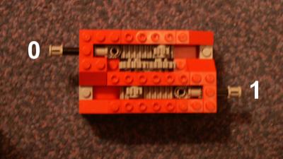
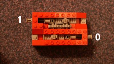
The NOT gate was the first and easiest gate to design. All you have to do is ensure that one push-rod does the opposite of the other as can be seen in the pictures.
The original NOT gate is very over-engineered and in many ways the NOT gate as an entity is redundant. On all the logic gates to NOT an input you only need to reverse the direction of the cog that drives the rack forward or backward. This is easily affected by simply having the input push-rod acting at the bottom or the top of the cog depending on which way you need the rack to move.
The cog's direction is different in each case, so any rack that the cog acts on will also move in an opposite direction. This is exactly the motion we require when NOTing an input. The only time an output needs to be NOTd is if we are't going to use it as an input to another gate, even then, with the available gates, a NOT gate shouldn't be required.
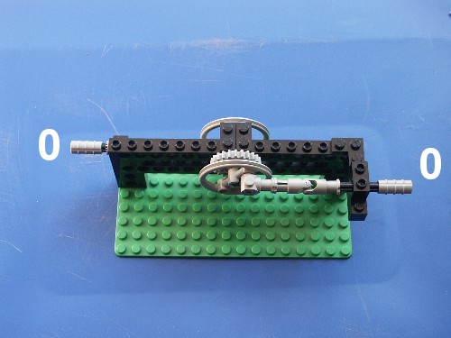
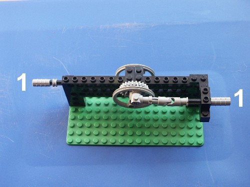
The buffer gate is effectively a modification of the NOT gate and there are several ways to construct them. I chose a simple system of differently sized cogs (24 and 8 tooth), but levers would work equally well. The idea is to take a half-stud input and convert it to a one-stud output, thereby creating an in-line amplification, albeit passively. The pictures should show this more clearly, alternatively you can watch the video of the buffer in action.
The OR and NAND gate related, one is simply the other with NOTd inputs, which is why they're both in this section.
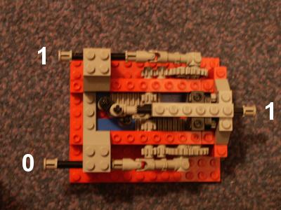
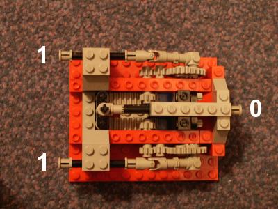
The OR gate
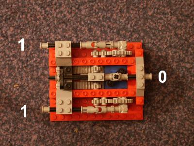
The OR gate was the first logic gate I designed that actually does something. I decided to make the OR gate after the NOT gate because with these two you can make NAND, AND, and NOR gates.
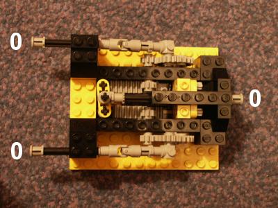
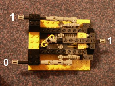
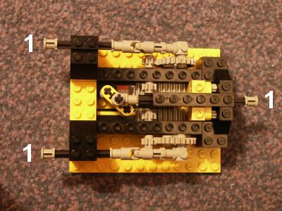
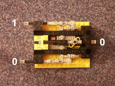
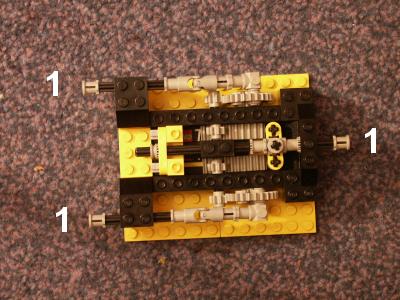
The key mechanism in the OR gate is the rotation of one of the cross-beams. This allows either input rod to go back or forward, separately, without changing the position of the output rod. The fixed cross-beam at the other end of the shaft will move forward regardless of whether it is pushed by one or both input rods. The four input and output states are shown on the figures below.
The step-by-step instructions on how to build the model are available for downloading.
And if you're keen to see it in action there is also a video available to watch.

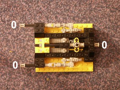
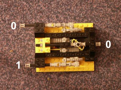
The NAND gate
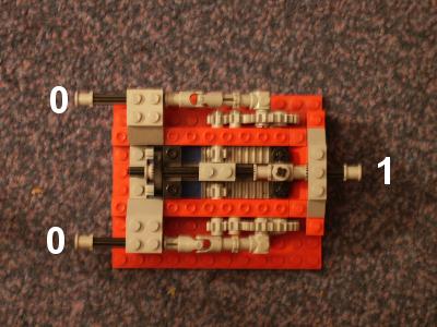
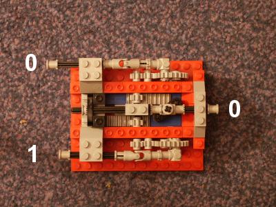
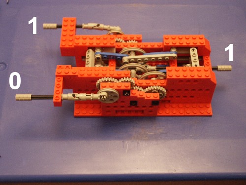
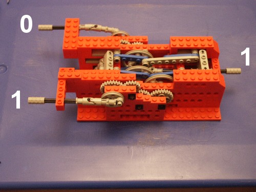
Logically a NAND gate is the same as an OR gate with NOTd inputs. This is a very useful equivalence. There are two ways I could have done this to my OR gate. The easiest is to use the NOT gate at each input. The other way was by recognising that to NOT the inputs just requires an extra cog in each gear train, to reverse the motion of the racks. This should be clear from the four logic states shown in the photos.
Unfortunately, by using extra cogs, the gate suffers from the tiny amount of slack in the gears. This reduces the linear motion of the push-rods to the extent that after two gates in series everything grinds to a halt.
The step-by-step instructions on how to build the model are available for downloading.
There is also a video available to watch.

Just as the OR gate and NAND gates are related, so to are the AND gate and NOR gate, and as such both are featured in this section.
The AND gate
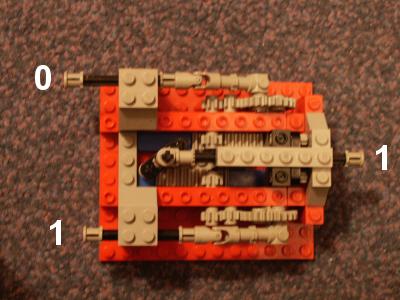
It might appear to be a simple matter to just NOT the output of the >NAND gate and get an AND gate. But, if you reverse the internal shaft mechanism of the OR gate, interchanging the position the fixed and rotating beam, then the OR gate becomes an AND gate! What's more it means that a NAND gate can now be made with fewer parts than previously (one NOT+AND,versus two NOTs+OR).
The step-by-step instructions on how to build the model are available for downloading.
There is also a video available to watch.
The NOR gate
Like the NAND gate, the NOR gate can be made simple by NOTing the OR gate output. However, just as the NAND gate can also be made by NOTing the inputs of the OR gate, if the inputs of the AND gate are NOTd then you get a NOR gate. Again this can be achieved by using the NOT gates or by adding an additional cog into the gear train.
The step-by-step instructions on how to build the model are available for downloading.
There is also a video available to watch.

The XOR gate
The XOR gate differs from a normal OR gate in that the 1,1 input gives a zero out. The XOR gate is of great importance as it is a fundamental component of the adder.
This was the most difficult gate to build, mainly because it is a composite gate made from two ANDs, two NOTs and an OR gate. Sure I could have made it that way, but this isn't satisfactory and given the inertia and gear slippage, it meant that a half adder was probably never going to happen. But around Jan 05 I finally cracked it.
The gate makes use of a sort of lever system. These are pushed from their top or bottom and will rotate about their centre if pushed only from either. Here's the trick, if the lever is pushed from the top and bottom at the same time it will move laterally. OK that's not the clearest of explanations, but hopefully the photos below, which show the gate in its four possible states along with a cut away photo showing the internal workings will make things more lucid. Failing that have a look at the XOR gate video that is available to download.


The Flip-Flop
The flip-flop is a composite logic gate usually made from NANDs or NORS. As with the half adder, without flip-flops modern computing wouldn't exist.
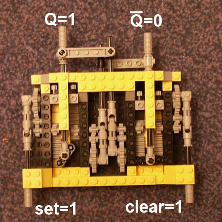
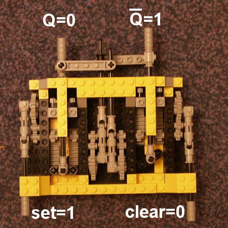
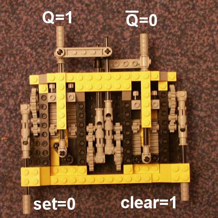
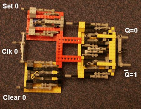
Once you have a nice simple working NOR or NAND gate then building Flip-Flops (FF) becomes a simple matter. In computing FFs are pretty important since they form the basis of memory. A FF is a device made with either two NOR or two NAND gates. Most FFs are made using NAND gates and there are several different types. The basic operation takes the output of one gate as the input of the other gate and vice versa. This means a FF has two inputs and two outputs. The pictures of the LEGO FF should show what's going on along with the description below.
The initial set up of the FF is Set=1, Clear=1 and Q=1, Qbar=0.
Pulse Clear to 0. This makes Q=0 and Qbar=1, notice now that since the right hand NAND output is 1, Clear will have no effect on either Q or Qbar.
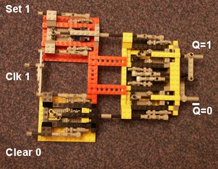
Now pulse Set to 0. This turns Q=1 and Qbar=0. In this case the left hand NAND gate output is 1 and so changing the value of Set will not do anything.
The Clocked Flip-Flop
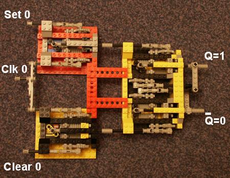
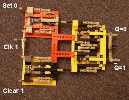
If you look at any digital electronic book, you'll soon see that anything useful tends to make use of a clock pulse to synchronise everything. The clock input is separate from the logic inputs, but they are related. A simple way to implement a clock is by using two NAND gates. Doing this changes the set and clear operations from working on a 0 to 1 transition to working on a 0 to 1 transition. The clocked Flip-Flop examples should show what's happening along with their descriptions below.
The initial set up of the FF, Set, Clock (clk), Clear and Qbar are at a logic level of 0 and Q is 1.
Pulse Clear to 1, then pulse to Clock (clk) to 1. This makes Q=0 and Qbar=1. Just as before the right hand NAND output is 1, so the Clear will have no effect on either Q or Qbar.
The Clock goes to 0 and then Clear goes to 0. It has to be done in this order to prevent the outputs becoming indeterminate.
Now pulse Set to 1 and the clk to 1. This turns Q=1 and Qbar=0. The left hand NAND gate output is 1 and so changing the value of Set will not do anything.
The Clock goes to 0 and then Set goes to 0. Just as before it has to be done in this order to present the outputs becoming indeterminate.
It is possible to build an edge detector for the Clock signal. It requires a few more NAND gates. The advantage of doing this is that it no longer matters when the Clock signal goes back to 0 and the indeterminate state is avoided.
The Half adder
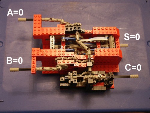
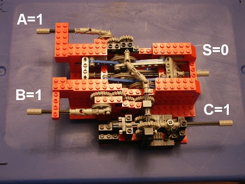
The half adder is a fundamental building block of computing. The device is made from an XOR gate and an AND gate. There are two inputs, which are fed into both the XOR and the AND gate. There are also two outputs, one from the XOR gate and one from the AND gate. The XOR output is called the sum, S and the AND output is called the carry, C.
The device adds binary numbers, as the name suggests! That is, in the case of adding two bits together, the sum of 0+0 = 0, carry 0; 0+1 = 1, carry 0; 1+0 = 1, carry 0 and 1+1 = 0, carry 1. Unfortunately it can only add two bits, which obviously limits its usefulness. However, by combining two half adders, one can get a full adder, which in turn can be cascaded to produce a binary adder of any size.
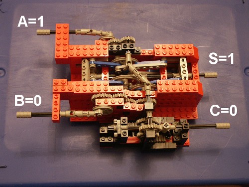
The pictures above show the LEGO half adder in its four different states, where A and B are the inputs, S is the sum and C is the carry bit.
There is also a video available of it being operated.

Powered Push-Pull Gates
The push-pull logic gates suffer from two significant problems. The first is inertia, the second is output attenutaion. Icreased inertia means that as more gates are added a greater and greater force on the first gate's input is required to affect the last gate's output. The output attenutation is a consequence of slippage in the mechanism, such as in the gears. This splippage error is cumulatative meaning that after a few gates a change in logical state in the first may not change anything in the last.
To overcome both these problems a means to power the gates is necessary. To achieve this I've used linear accuators to take a rotational input to drive the push-pull logic mechanism. The logic then switches the driection of the output rotation hence changing the rotating logic state on the inputs of the next gate in the circuit.
In effect there is a unification between the push-pull system and the rotational system which allows for more complicated feedback gates like flip-flips to be created.
Rotational LEGO Logic Gates
"The wheels on the bus go round and round ..." - Traditional
The push-pull logic gates suffer from a great disadvantage, that is inertia. The only way round this is to have some sort of amplifier, the mechanical equivalent of the +ve line on a circuit board. Unfortunately with the push-pull system this is virtually impossible. Instead I've gone right back to the drawing board and considered using rotation to represent the logic states.
I've taken the rotation of an axle, in any direction, to represent a logical one and the absence of rotation (i.e. the axle is stationary) to be a logical zero. This has meant buffering is much more easy to achieve.
I've found no other web pages detailing using rotation to represent logic other than ideas presented for discussion. No one it seems has actually built anything and if they have it isn't on the internet as far as I am aware. Ok that's not quite true, the web page, has details of a LEGO NOT gate. And this page has a rotational AND gate os\f sorts, but it is exceedingly complex compared to my own.
The underlying concept behind my rotational logic gates is the addition and subtraction of rotations. This isn't a new idea, there are other sites that have examples of this and people in their kindness have suggested it to me. Essentially, such additions and subtractions allows one to build up a series of outputs to represent, probably, anything you like for a set of inputs. Each of the logic gate pages shows the basic algebra involved.
I've recently obtained an out-of-print book - "Computing mechanisms and Linkages" by Antonin Svoboda, which illustrates and explains many principles and techniques of mechanical computation, including the methods I've used.
If you made any mechanical logic gates using rotation then please contact me.
The details of the rotational logic gates can all be found on the this page.
Addition, Subtraction and Absolute Value
The underlying mechanisms used in the construction of the rotational logic gates do nothing more than add or subtract the rotations of axles.
I've taken the rotation of an axle, in any direction, to represent a logical one and the absence of rotation (i.e. the axle is stationary) to be a logical zero. Whilst the direction of rotation is unimportant, mixing directions in a single mechanism can cause all sorts of problems.
There are three mathematical operations with axle rotations in this section: addition, subtraction and absolute value. The last, is particularly useful since subtraction can lead to the situation where equivalent logic outputs are rotating in different directions and this can completely screw up the operation of any subsequent gate.
The mathematics for addition and subtraction is achieved by using a differential gear, this is about the only effective way to decouple and/or couple axle rotations. The absolute value is created using a one-way-gear mechanism.
Also demonstrated is a simple on/off toggle switch. It's included in this section due to its use in initiating logical zero/sone states.
With the mechanisms describe on this page it is, in theory, possible to create and operate any boolean logic function you might want (amongst other things of course!).
Addition
When the two axles that link to the internal gears of a differential gear rotate in the same direction, the housing also rotates. It does so at speed equal to half the sum of the individual axle speeds, hence the output must be doubled. Easy enough with 16 and 8 tooth cogs. Here is the addition table:
A B 0.5 x (A + B) 0 0 0 0 1 1/2 1 0 1/2 1 1 1
That looks suspiciously like the truth table for an OR gate! It nearly is, just a little more in the way of mechanics and maths will get us there as the Rotational OR gate section describes.
It is probably easier to understand the addition mechanism by watching a video of it in action.
Subtraction
To move from addition to subtraction is just a matter of reversing the direction of rotation for one of the input axles. When one of the axles that link to the internal gears of a differential gear is reversed, the housing stays stationary. When the inputs rotate in opposite directions, the housing then turns. In the table below you can read + as clockwise and - as counter-clockwise. Just as with the adder, when the housing does rotate, it does so at speed equal to half the sum of the individual axle speeds, hence the output must be doubled. Again, this is easy enough with 16 and 8 tooth cogs. Here is the subtraction table:
A B 0.5 x (A - B) 0 0 0 0 +1 -1/2 +1 0 +1/2 +1 +1 0
Now doesn't that table look like the truth table for an XOR gate?! All that has to be done is to double the output rotation speed so it is the same as the input and other than the pesky sign changes, it is an XOR gate as explained in the XOR gate section on this page.
And if you're keen to see the subtraction mechanism in action there is a video available to watch.
Absolute value
To get the absolute value of a rotation a mechanism know as a one-way or unidirectional gear can be used. There have been many examples of these published on the web over the years. Essentially, all the mechanism does is take an input rotation of any direction and supply an output that always rotates in the same direction. There are two ways (that I know of) that this can be done. The first, as shown here, uses two sets of gears (see the video below). One set is pivoted and will drive a different gear depending on which way the input is rotating. The second uses a worm gear rather than a pivoted gear train. I suspect the latter is more robust, but it suffers from quite a long lag when the input changes direction. A nice explanation of the second method can be found here. This site also has details of a rotational adder/subtractor too.
You can use these instructions to build a version of the mechanism.
The table of input to out values is straight forward!
A abs(A) = |A| +1 +1 -1 +1
And if you're keen to see my absolute value mechanism in action there is a video available to watch.
Switches
The toggle switch is essentially a single pole, single throw switch. Whilst not a mathematical operation, these switches are fundamental for the initiating of logic states.
My switch makes use of the Technic clutches or drive shafts (I'm not sure of their proper name). Usually these are used in gear boxes to allow seemless shifting between different gear ratios, but they are also use to switch between different motorised functions in some of the newer Technic models such as the gargantuan Bucket Excavator. In the case of the toggle switch illustrated here one end is simply fixed (logical zero), whilst the other is free to rotate (logical one).
The following video shows the switch in action.
The rotational NOT gate can be constructed from a subtraction. However, to do so requires one of the inputs to always be rotating. That is, the NOT gate is powered, i.e a +ve line. There is an obvious advantage to this, it means that the mechanisms can get extra power or rotation boosts. As with all differential gear operations, the output is halved and so must be scaled up by 2:1 using a 16 tooth to 8 tooth gear train or equivalent gear ratio. The following table should hopefully make all this a bit more clear.
+ve A X = 0.5 x (+ve - A) NOT A = X x 2 1 0 1/2 1 1 1 0 0
The following video shows the NOT gate in operation.
The rotational OR gate can be constructed from two addition, one subtraction and an absolute value. Before finally scaling up the output by 2:1 using a 16 tooth to 8 tooth gear train or equivalent gear ratio. The following table should make this clearer.
A B X = 0.5 x (A + B) Y = 0.5 x (A - B) Z = 0.5 x (X + |Y|) A OR B = Z x 2 0 0 0 0 0 0 0 1 1/2 -1/2 1/2 1 1 0 1/2 1/2 1/2 1 1 1 1 0 1/2 1
This video shows the OR gate in operation.
The rotational AND gate can be constructed from one addition, two subtractions and an absolute value. Before finally scaling up the output by 2:1 using a 16 tooth to 8 tooth gear train or equivalent gear ratio. The following table should help explain.
A B X = 0.5 x (A + B) Y = 0.5 x (A - B) Z = 0.5 x (X - |Y|) A AND B = Z x 2 0 0 0 0 0 0 0 1 1/2 -1/2 0 0 1 0 1/2 1/2 0 0 1 1 1 0 1/2 1
The following video shows the AND gate in operation.
The rotational XOR gate is the simplest to construct. It takes no more than a simple subtraction and an absolute value to create one. Before finally scaling up the output by 2:1 using say a 16 tooth to 8 tooth gear train. The following table should help explain.
A B X = 0.5 x (A - B) A XOR B = |X| x 2 0 0 0 0 0 1 -1/2 1 1 0 1/2 1 1 1 0 0
The following video shows the XOR gate in operation.
Adders
You may have noticed that the rotational AND gate has the sum output of a half adder already embeded within the mechanism. Not only that it also uses exactly the same construction and underlying mechanism as the AND gate! This is nice since usually a half adder requires both an AND gate and an XOR gate separately. Once a half adder is constructed it is a simple matter using another OR gate to implement a full adder.
Implementations of both the half adder and full adder are represented in this section.
Half-adder
The following table below shows how the half adder is built from subtractions, additions and and absolute value.
A B X = 0.5 x (A + B) Y = 0.5 x (A - B) Z = 0.5 x (X - |Y| ) Sum = |Y| x 2 Carry Out = Z x 2 0 0 0 0 0 0 0 0 1 1/2 -1/2 0 1 0 1 0 1/2 1/2 0 1 0 1 1 1 0 1/2 0 1
The following video shows the Half adder operating.
Full adder
The full adder can be constructed by combining two half adders with an OR gate as any course on digital logic will tell you. Combining the rotational LEGO logic gates for these operations would require nine differential gears. This seemed to be too many, after all the full adder is esentially nothing more than an extended 'half adder' with three inputs, A, B, and Carry In (Cin); and two outputs SUM and Carry Out (Cout).
Recall, the half-adder can be made using two subtractions and one addition. Bearing this in mind I went back to the addition and subtraction of rotations finding that it's fairly easy to subtract three inputs and add three inputs to produce a 1-bit (full) adder. Two additions, three subtractions and two absolute values are required, which uses just five differential gears, a huge saving on the nine needed using the combination of fundamental gates.
In fact, this saving gets better for every bit to be added. For example 2-bit adder constructed this way would require just two more differential gears, for a total of seven. In general an n-bit adder (for n>=1) uses 2n+3 differential gears and n+1 absolute value operations.
The table below shows the calculations operations needed to implement the full adder.
The following video shows the Full adder operating.
A B Cin X' = A + B X = X' + Cin Y' = A - B Y = |Y'| - Cin SUM = |Y| Cout= 0.5 * (X - SUM) 0 0 0 0 0 0 0 0 0 0 0 1 0 1 0 -1 1 0 0 1 0 1 1 -1 1 1 0 0 1 1 1 2 -1 0 0 1 1 0 0 1 1 1 1 1 0 1 0 1 1 2 1 0 0 1 1 1 0 2 2 0 0 0 1 1 1 1 2 3 0 -1 1 1
Share and donate!